Verified 2026-10
m5stack ESP32-PICO-D4 Atom Matrix ESP32 Dev Kit v1.1
24.0 x 24.0 mm ESP32-PICO-D4 board with a 5x5 WS2812C RGB matrix, a BMI270 IMU at 0x68, an IR emitter on G12, one Grove/HY2.0-4P port and USB-C - $14.95 USD.
Place this board on a carrier in the editor →
Part & documents
| Headline part | ESP32-PICO-D4 |
|---|---|
| Data sheet | ESP32-PICO-D4 data sheet → |
| Source | shop.m5stack.com/products/atom-matrix-esp32-dev-kit-v1-1 → |
Specs
| MCU | Espressif ESP32-PICO-D4 (dual-core Xtensa LX6 up to 240 MHz, 520 kB SRAM, 4 MB SPI flash in package, 2.4 GHz Wi-Fi) |
|---|---|
| Clock | 240 MHz |
| RAM | 520 KB |
Pinout
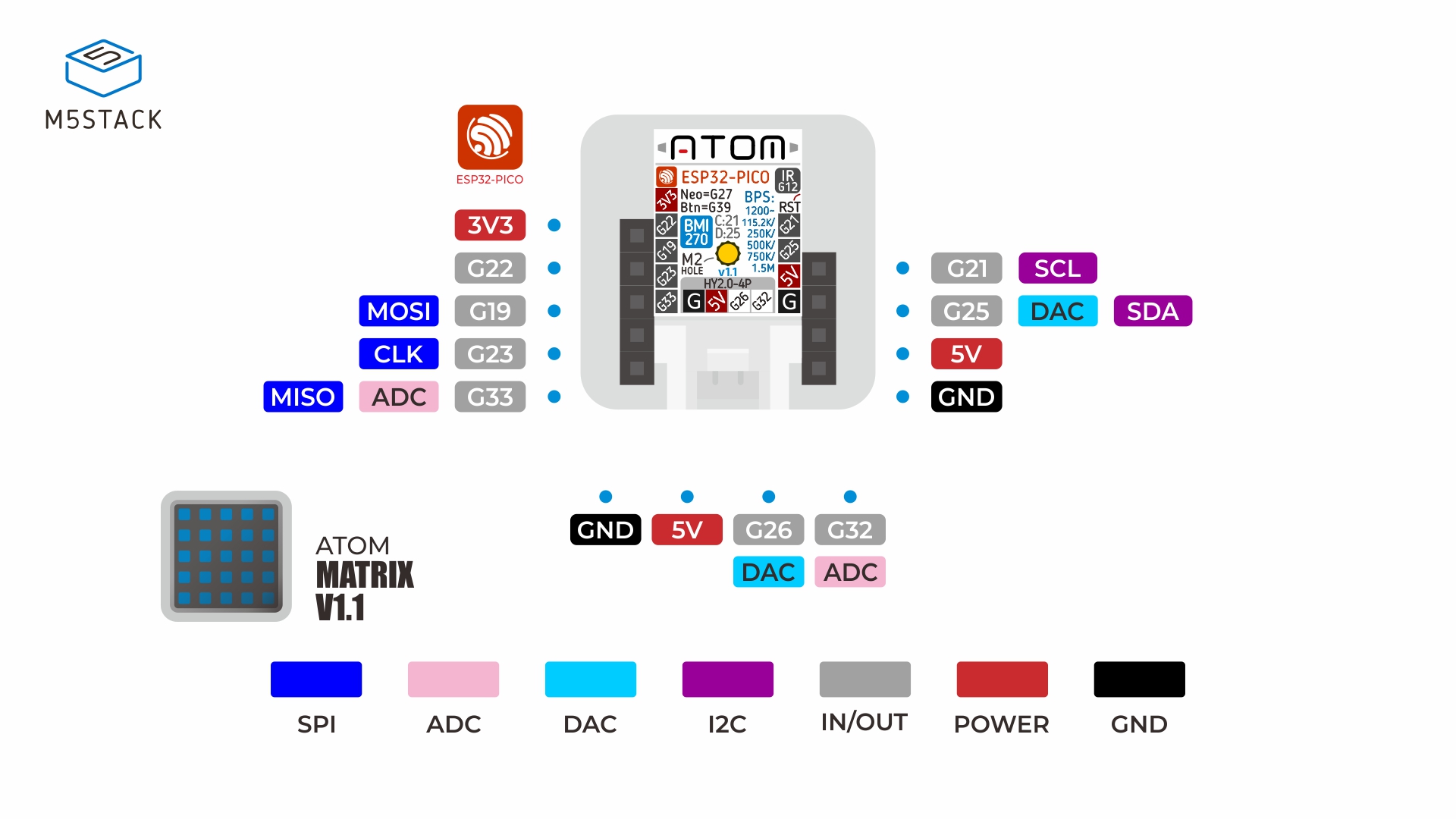
13 pads, as the vendor numbers them.
| # | Name | Function | Signals |
|---|---|---|---|
| 1 | 3V3 | 3.3 V rail output, left edge, top | |
| 2 | G22 | GPIO22, left edge, second from top | |
| 3 | G19 | GPIO19, SPI MOSI, left edge, third from top | |
| 4 | G23 | GPIO23, SPI CLK, left edge, fourth from top | |
| 5 | G33 | GPIO33, SPI MISO, ADC-capable, left edge, bottom | |
| 6 | G21 | GPIO21, I2C SCL, right edge, top | |
| 7 | G25 | GPIO25, I2C SDA, DAC-capable, right edge, second from top | |
| 8 | 5V | 5 V input/output rail, right edge, third from top | |
| 9 | GND | ground, right edge, bottom | |
| 10 | GND | ground, HY2.0-4P, black wire | |
| 11 | 5V | 5 V rail, HY2.0-4P, red wire | |
| 12 | G26 | GPIO26, DAC-capable, HY2.0-4P, yellow wire | |
| 13 | G32 | GPIO32, ADC-capable, HY2.0-4P, white wire |
Buses
| Bus | Signals | Pins | Voltage | Note |
|---|---|---|---|---|
| I2C ×1 | SDA, SCL | G25, G21 | 3.3 V V | One bus on G21 (SCL) and G25 (SDA), carrying only the on-board BMI270 at 0x68. The HY2.0-4P port is not on it: M5Stack's pin table puts G26 and G32 on that connector, which are not the I2C pins. |
I²C / bus addresses
| Address | Bus | Device | Note |
|---|---|---|---|
| 0x68 | I2C | Bosch BMI270 six-axis IMU |
Power
| Input | 5 V at 500 mA maximum on USB Type-C |
|---|---|
| Typical draw | 61.65 mA |
Notes
M5Stack publishes no pad numbers for this board: the PinMap drawing carries only GPIO net names (3V3, G22, G19, G23, G33 on one edge; G21, G25, 5V, G on the other; GND, 5V, G26, G32 on the HY2.0-4P), read with a vision model at 1920x1080 and recorded as kind: image, so the 1-13 numbering here is this entry's own sequence and each description names the edge and position. The docs page's 'Schematics' link is not this board: it opens a PDF whose title block reads 'ATOM KEYPAD.SchDoc' (a WS2812B chain on another PCB), so no reference circuit for the Matrix is published and none is claimed. M5Stack's own spec table calls the connector 'Grove (I2C+I/O+UART)' while its pin table puts G26/G32 on it - the port is general-purpose I/O, not a second I2C socket. The vendor warns that high RGB brightness damages the LEDs and the acrylic, and that an FTDI VCP driver is needed on some hosts.
AI context
Dense context for pasting into a model prompt — addresses, pinout, voltages, tolerances and the vendor's reference circuit.
PART: M5Stack Atom-Matrix v1.1, SKU C008-B-V11, a 24.0 x 24.0 x 13.9 mm cube-shaped board built on the Espressif ESP32-PICO-D4 system-in-package - dual-core Xtensa LX6 at up to 240 MHz, 600 DMIPS, 520 kB SRAM, 4 MB SPI flash inside the package, 2.4 GHz Wi-Fi and a 3D antenna. The board adds 25 x WS2812C-2020 RGB LEDs in a 5x5 matrix, a BMI270 six-axis IMU, an IR emitter, one programmable button under the matrix, a USB Type-C port and one HY2.0-4P (Grove) connector; it is the v1.1 revision that replaced the v1.0 board's MPU6886 with the BMI270.
ADDRESSES: one I2C device on the board, the BMI270 IMU at 7-bit 0x68, on G21 (SCL) and G25 (SDA). Nothing else on the board answers I2C, and the HY2.0-4P port is not on that bus, so a Grove I2C device plugged into it will not be seen on the IMU's pins.
PINOUT: M5Stack publishes this board's pad labels only in its PinMap drawing - there are no pad numbers anywhere in the vendor's documentation, so the numbers here are this entry's own sequence and every description names the edge and position of the pad. Left edge, top to bottom: 1 = 3V3, 2 = G22, 3 = G19 (SPI MOSI), 4 = G23 (SPI CLK), 5 = G33 (SPI MISO, ADC-capable). Right edge, top to bottom: 6 = G21 (I2C SCL), 7 = G25 (I2C SDA, DAC-capable), 8 = 5V, 9 = GND. The HY2.0-4P port, wired black-red-yellow-white: 10 = GND, 11 = 5V, 12 = G26 (DAC-capable), 13 = G32 (ADC-capable). Inside the case and not on any header: G27 drives the LED matrix data line, G39 is the button, G12 is IR_TX.
SUPPLY: 5 V at 500 mA maximum into the USB Type-C port; measured consumption 5 V at 61.65 mA. The 3V3 pad on the left edge is the regulated 3.3 V rail for external sensors, not an input. Operating temperature 0 to 60 C.
LOGIC: 3.3 V I/O from the ESP32-PICO-D4 on every GPIO pad; the 5V pad is the USB/rail input, not a 5 V logic level, so anything driving or driven by G19/G21/G22/G23/G25/G26/G32/G33 must be 3.3 V. G33 and G32 are the ADC-capable pads, G25 and G26 are the DAC-capable pads.
REFERENCE CIRCUIT: M5Stack publishes no usable schematic for this board - the 'Schematics' link on the Atom-Matrix v1.1 documentation page opens a PDF whose title block reads 'ATOM KEYPAD.SchDoc' and whose sheet is a chain of WS2812B LEDs on a different PCB, so no pull-up, decoupling or regulator figure for the Matrix itself is obtainable from the vendor and none is recorded here. The 25 WS2812C-2020 LEDs have their own data sheet on the same page. A USB-serial driver (FTDI VCP) is required on some hosts before the port enumerates.
TRAPS: (1) M5Stack warns that driving the RGB matrix at high brightness can damage both the LEDs and the acrylic display - it recommends a moderate brightness, and the Atom-Matrix library maps brightness to 0-100. (2) The documentation's specification table calls the connector 'Grove (I2C+I/O+UART)', but the board's own pin table puts G26 and G32 on it, which are not the I2C pins (G21/G25) - treat the port as general-purpose I/O with 5 V and GND, not as a second I2C socket. (3) There are no pad numbers in any vendor document, so any pin number quoted from this page is a sequence, not silkscreen. (4) The board is 24 mm square with a single M2 mounting hole; the header pads are on the two opposite edges and the USB-C port and Grove socket face the same direction.
OTHER: 25 x WS2812C-2020 at 2020 package size, IR emitter on G12, one user button on G39, product weight 7.3 g. Supports UiFlow1, UiFlow2, Arduino IDE, ESP-IDF and PlatformIO (board id m5stack-atom).
Provenance
Every figure on this page was read from the 6 sources below and last checked on Oct 25, 2026.
- product M5Stack store product page (price, USD)
- reference M5Stack docs - Atom-Matrix v1.1 (specifications, GPIO pin table)
- image M5Stack PinMap drawing (pad labels, read by vision - no pad numbers printed)
- datasheet Espressif ESP32-PICO series datasheet
- datasheet Bosch BMI270 datasheet
- reference 'Schematics' link on the docs page - actually ATOM KEYPAD.SchDoc, a different board