Verified 2026-10
Grove - 4-Channel SPDT Relay
Four changeover relays behind one Grove I2C socket: an on-board controller fetches I2C commands and drives four SPDT switches, each brought out to its own 3-way screw terminal rated 10 A at 250 VAC / 30 VDC, while the module itself runs on 5 V and takes its address from 0x00-0x7F.
Place this board on a carrier in the editor →
Specs
| MCU | MindMotion MM32F031F6P6 — Seeed states the STM32F030F4P6TR was replaced by the MM32 because of the ST shortage, and that the factory firmware differs per chip |
|---|
Pinout
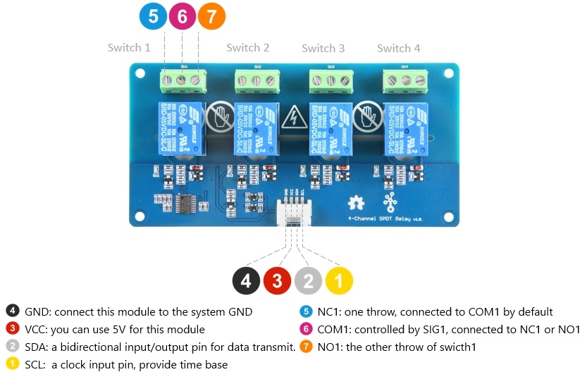
7 pads, as the vendor numbers them.
| # | Name | Function | Signals |
|---|---|---|---|
| 1 | SCL | I2C clock, Grove socket | I2C SCL |
| 2 | SDA | I2C data, Grove socket | I2C SDA |
| 3 | VCC | Supply for the module: "you can use 5V for this module" | 5 V supply |
| 4 | GND | Ground | ground |
| 5 | NC1 | Switch 1's normally-closed throw — Seeed: "one throw, connected to COM1 by default" | relay 1 NC |
| 6 | COM1 | Switch 1's common, driven between NC1 and NO1 by SIG1 — "controlled by SIG1, connected to NC1 or NO1" | relay 1 COM |
| 7 | NO1 | Switch 1's normally-open throw — "the other throw of swicth1" (Seeed's own typo) | relay 1 NO |
Buses
| Bus | Signals | Pins | Voltage | Note |
|---|---|---|---|---|
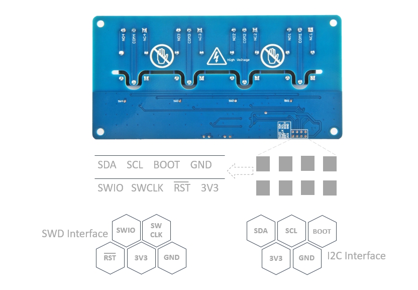
| I2C ×1 | SDA, SCL | SDA, SCL | 5 V | the Grove socket is the module's only control path; the back of the PCB carries a second I2C header that actually works as the boot UART, which needs BOOT held high |
I²C / bus addresses
| Address | Bus | Device | Note |
|---|---|---|---|
| 0x11 or 0x12 | I2C | on-board relay controller (MM32F031F6P6) | written exactly as Seeed's spec table writes the default. Their worked example scans and reports a device found at 0x12, while the code printed on the same page writes 0x11 — which one a given unit answers at is not pinned down by the docs. Changeable over 0x00-0x7F and saved to flash (changeI2CAddress, which needs the current address to write a new one); Seeed warns the address must be set before use if you want it changed. |
Power
| Input | 5 V on Grove pin 3 (VCC) |
|---|---|
| Input range | 5 V |
Seeed publishes "Nominal Coil Current 89.3 mA" and "Power Consumption abt. 0.45 W" but no board-level typical draw, so none is recorded and the two published figures are not reconciled here. Load side: TUV 10 A 250 VAC / 10 A 30 VDC, UL 10 A 125 VAC / 28 VDC, max allowable 250 VAC / 110 VDC, contact resistance 100 mOhm max, insulation resistance 100 MOhm min at 500 VDC, contact material AgCdO, 30 operations/min max, -40 to +85 C, 45-85 %RH.
Notes
Pin numbers 1-4 are the 4-pin Grove socket in the vendor's pin-map order (1 SCL, 2 SDA, 3 VCC, 4 GND — the standard Grove I2C order, and the same order as Seeed's direct-connection table of SCL yellow / SDA white / 5V red / GND black). Pins 5-7 are the three screws of Switch 1, numbered as that pin map numbers them; switches 2-4 repeat it exactly (Seeed: "the switch 1-4 have the same pin function"), but only Switch 1 is labelled in the map and the board's own top edge is silkscreened NO n / COM n / NC n per channel. The twelve screws are mains terminals, not 2.0 mm pads. The back of the PCB carries one 2x4 header doing two jobs — SDA / SCL / BOOT / GND over SWIO / SWCLK / RST(active low) / 3V3 — where SWD is what Seeed flashes firmware through, and the I2C pair on that header is really the boot UART and needs BOOT high. Design trap: I2C is the module's only control path, so the bus has to be up before any relay does anything. Unsourced here: the rail the module's own SDA/SCL pull up to — Seeed publishes the working voltage as 5 V and drives it from a 5 V Seeeduino in the example, but never states that rail, so whether a 3.3 V bus works on it is not something these pages answer. Board silkscreen reads "4-Channel SPDT Relay v1.0".
Provenance
Every figure on this page was read from the 4 sources below and last checked on Oct 16, 2026.
- vendor Seeed — Grove - 4-Channel SPDT Relay product page (SKU 103020133, $12.90, in stock)
- reference Seeed wiki — Grove - 4-Channel SPDT Relay (spec table, I2C address, pin map note, firmware/MM32 swap)
- datasheet Seeed — Grove - 4-Channel SPDT Relay front pin map (Grove order SCL/SDA/VCC/GND, Switch 1 NC1/COM1/NO1)
- datasheet Seeed — Grove - 4-Channel SPDT Relay back pin map (2x4 SWD/I2C header: SDA SCL BOOT GND / SWIO SWCLK RST 3V3)