Verified 2026-10
Grove - Solid State Relay V2
One AC switch on a Grove cable: a single digital CTR line turns on an Omron G3MC-202P solid-state relay, which switches an isolated 0.1-2 A load at 75-264 VAC (rated 100-240 VAC 50/60 Hz) on a 2-position screw terminal; 40 x 20 x 23 mm, control input specified at 4-6 V, and the load side is AC only.
Place this board on a carrier in the editor →
Pinout
6 pads, as the vendor numbers them.
| # | Name | Function | Signals |
|---|---|---|---|
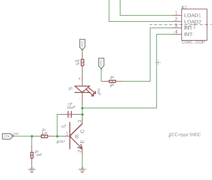
| 1 | CTR | Control input for the relay, through a 2.2 k series resistor into the BC817 base; Seeed's example drives it from a digital port (D7 on a Base Shield) | digital input, relay control |
| 2 | NC | Grove connector position 2 — the pin-map legend reads "not connected" | not connected |
| 3 | VCC | Supply for the module: "you can use 5V for this module" | 5 V supply |
| 4 | GND | Ground | ground |
| 5 | Load 2 | High-voltage screw terminal Seeed numbers 5 on the pin map (the left one as photographed) | AC load terminal |
| 6 | Load 1 | High-voltage screw terminal Seeed numbers 6 on the pin map (the right one as photographed) | AC load terminal |
Power
| Input | 5 V on Grove pin 3 (VCC), operating range 4-6 V; the AC load goes to the screw terminal and shares no conductor with the Grove cable |
|---|---|
| Input range | 4-6 V |
Seeed publishes the board's ratings but no board-level current draw, so none is recorded. Board's own numbers: rated load voltage 100 to 240 VAC 50/60 Hz, load voltage range 75 to 264 VAC, load current 0.1 to 2 A, leakage 1.5 mA max at 200 VAC, insulation resistance 1,000 MOhm min at 500 VDC, zero-cross switching, UL/CSA, 8.2 g. The relay underneath is an Omron G3MC-202P and Seeed hosts its datasheet for this board: 5 VDC input at 300 ohm +/-20 %, must-operate 4 V max, must-release 1 V min, ON-state drop 1.6 V RMS max, 30 A inrush (60 Hz, one cycle), 2,500 VAC dielectric strength input-to-output for one minute. Those are the relay's figures and the Grove board puts a BC817 plus a 0-ohm link in front of the input, so they are not the board's control current.
Notes
Pin numbers 1-4 are the 4-pin Grove socket in the vendor's own pin-map order (1 CTR, 2 NC, 3 VCC, 4 GND, i.e. the usual Grove convention of signal on pin 1 and ground on pin 4); 5 and 6 are the two mains screws, which Seeed numbers in the same pin map as Load 2 and Load 1. Only 1-4 sit on the 2.0 mm Grove grid — the screw terminal does not, and the board silkscreens only "SW" beside it, with "High Voltage" and a shock triangle at that end. The two load screws are the two ends of one switch, so which one gets line and which gets load is not a polarity. Vendor self-contradictions, recorded rather than resolved: the wiki prose says CTR is "pulled down by the 10k R2" while the schematic in that same wiki makes R2 the 1 k LED resistor and R3 the 10 k pull-down; and the prose says BC817-40 where the schematic says BC817. Unsourced here: whether a 3.3 V GPIO still switches it — the only published figure is the 4-6 V operating input, and a 3.3 V signal is below that. The product page itself now shows "Out of stock" and the discontinued block, and Seeed publishes no replacement, so this module cannot be bought new today.
Provenance
Every figure on this page was read from the 5 sources below and last checked on Oct 16, 2026.
- vendor Seeed — Grove - Solid State Relay V2 product page (SKU 103020137, $18.60, out of stock / discontinued)
- reference Seeed wiki — Grove - Solid State Relay V2 (spec table, hardware overview, schematic description)
- datasheet Seeed — Grove - Solid State Relay V2 pin map (Grove order CTR/NC/VCC/GND, screw terminals Load 2 / Load 1)
- datasheet Seeed — Grove - Solid State Relay V2 schematic (G3MC-202P K1 with LOAD1/LOAD2/INT+/INT-, R1 2.2 k, R2 1 k, R3 10 k, R4 0R, Q1, status LED)
- datasheet Omron — G3MC solid state relays datasheet (G3MC-202P ratings; the PDF Seeed publishes for this board)