Verified 2026-10
Pixy2 CMUcam5 - Smart Vision Sensor - Object Tracking Camera for Arduino, Raspberry Pi
A stand-alone vision module rather than a bare sensor: an NXP LPC4330 dual core at 204 MHz runs colour-blob and line tracking on-board at up to 60 fps and hands the result to a host over UART, SPI, I2C, USB or analog/digital, so the host never handles pixels; 140 mA typical, powered from USB 5 V or an unregulated 6-10 V on Vin, 1.5 x 1.65 x 0.6 in, 10 g.
Place this board on a carrier in the editor →
Specs
| MCU | NXP LPC4330, 204 MHz, dual core |
|---|---|
| Clock | 204 MHz |
| Flash | 2 MB |
| RAM | 264 KB |
Pinout
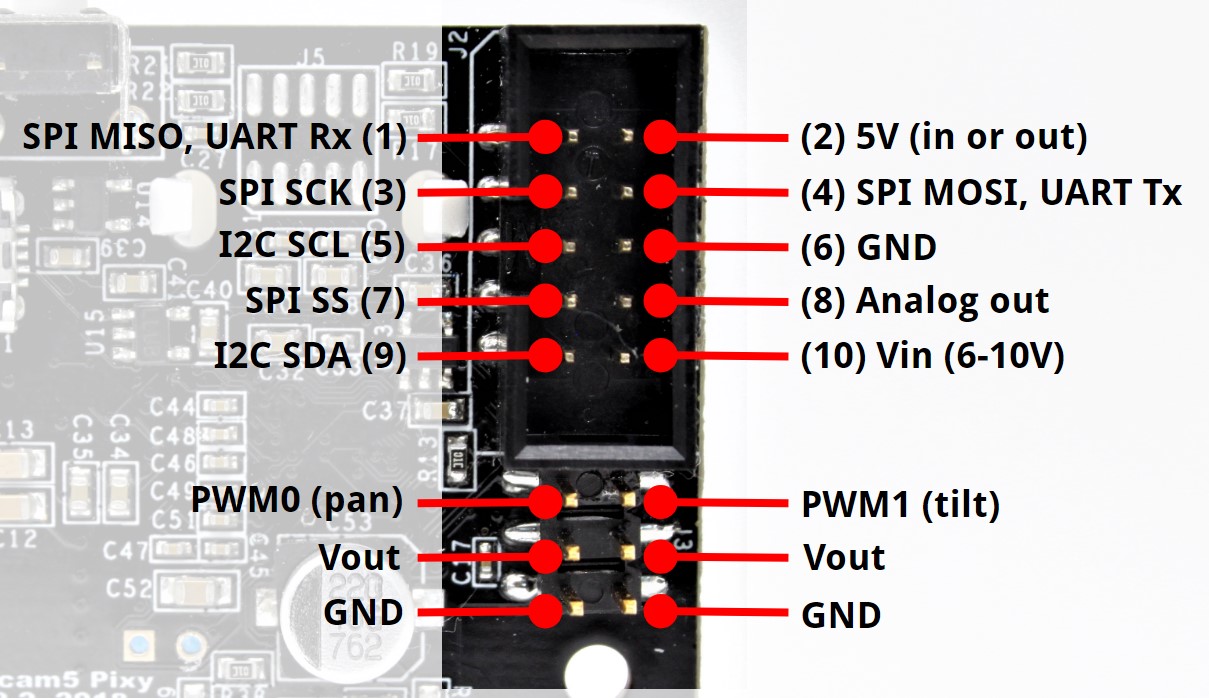
10 pads, as the vendor numbers them.
| # | Name | Function | Signals |
|---|---|---|---|
| 1 | SPI MISO / UART Rx | MISO for SPI, receive for UART; also the digital object-detected output (high 3.3 V when an object is seen) in analog/digital mode | SPI MISO, UART RX, digital output |
| 2 | 5V | 5 V rail, usable as an input to Pixy2 or as an output from it | 5 V in or out |
| 3 | SPI SCK | SPI clock, mode 3 | SPI SCK |
| 4 | SPI MOSI / UART Tx | MOSI for SPI, transmit for UART (0-3.3 V output) | SPI MOSI, UART TX |
| 5 | I2C SCL | I2C clock, 5 V tolerant | I2C SCL |
| 6 | GND | Ground — the pin Pixy's own wiring examples use as the return for every interface | ground |
| 7 | SPI SS | Slave select for the 4-wire SPI form, active low | SPI SS |
| 8 | Analog out | DAC output of the largest object's x or y position, 0-3.3 V, roughly 200 ohm impedance | analog output |
| 9 | I2C SDA | I2C data, 5 V tolerant | I2C SDA |
| 10 | Vin (6-10V) | Unregulated supply input, 6-10 V — the input to use when the host cannot supply 5 V | 6-10 V supply |
Buses
| Bus | Signals | Pins | Voltage | Note |
|---|---|---|---|---|
| SPI | MISO, MOSI, SCK, SS | 1, 4, 3, 7 | 3.3 V | SPI slave, mode 3, MSB first, SCK idle low, SS active low; 3.3 V outputs with 5 V-tolerant inputs. The default Arduino cable uses the 3-wire ICSP form with no slave select (pins 1, 3, 4 only); the 4-wire form takes SS on pin 7. 2 Mbit/s in the Pixy2 Arduino library by default. |
| I2C | SDA, SCL | 9, 5 | 3.3 V | I2C slave that must be polled. Weak 82 kOhm pull-ups to 5 V on SDA and SCL via R14/R15, and the signals are 5 V tolerant; the address is set in PixyMon's Interface tab and Pixy's docs state no default. Multiple Pixys need one address each. |
| UART | RX, TX | 1, 4 | 3.3 V | 8 data bits, 1 stop bit, no parity, no handshaking, up to 230 kbaud. RX (pin 1) is a 5 V-tolerant input; TX (pin 4) is a 0-3.3 V output. |
| USB | 5 V | micro USB on the back, always enabled; used by PixyMon for video and configuration and by libpixyusb2 on Linux hosts. |
Power
| Input | 5 V on pin 2 (labelled 5V, in or out) via USB, or unregulated 6-10 V on pin 10 (Vin) |
|---|---|
| Input range | 5 V USB, or 6-10 V on Vin |
| Typical draw | 140 mA |
140 mA typical is the vendor's whole-module figure and does not include pan/tilt servos, which the board drives from its own Vout pins (PWM0 pan, PWM1 tilt). Pin 2 is bidirectional 5 V, so a carrier that feeds 5 V into it while the USB cable is also connected has two supplies on one rail and Pixy's docs do not say which wins — power the module from one source only.
Notes
Pixy2 is made by Charmed Labs with Carnegie Mellon, and Seeed is a reseller, so the electrical figures here come from Pixy's own documentation rather than Seeed's listing; the pin functions and bus voltages were read from the v2 porting guide and the connector diagram it points at. Two lens variants share the Pixy2 name and neither Seeed's listing nor the pinout says which ships: Pixy 2.0 is 60 deg horizontal / 40 deg vertical, Pixy 2.1 is 80 / 55 — no field of view is recorded for that reason. The board is a camera with a processor, not a sensor with a register map: UART, SPI and I2C all carry the same binary packet protocol (2-byte sync 0xc1ae without checksums, 0xc1af with; packet type, length, payload; little-endian; response latency under 100 us), up to 7 colour signatures and objects indexed 0-255. Integrated light source rated about 20 lumens; sensor is an Aptina MT9M114 at 1296 x 976. The address is configured in PixyMon and Pixy does not publish a default, so addresses stays empty rather than carrying a guess.
Provenance
Every figure on this page was read from the 4 sources below and last checked on Oct 17, 2026.
- vendor Seeed — Pixy2 CMUcam5 product page ($79.00, in stock; 10+ price $75.00)
- reference Pixy (Charmed Labs) — Pixy2 overview technical specs (LPC4330 204 MHz, MT9M114, 140 mA typical, USB 5 V or 6-10 V, 264K RAM, 2M flash, dimensions, weight, 20 lumen light)
- reference Pixy — How to talk to Pixy2 porting guide (pin functions, SPI mode 3, 82 k pull-ups, UART 8N1 up to 230 kbaud, packet protocol)
- datasheet Pixy — Pixy2 I/O connector pinout diagram (1 MISO/Rx, 2 5V in-or-out, 3 SCK, 4 MOSI/Tx, 5 SCL, 6 GND, 7 SS, 8 analog out, 9 SDA, 10 Vin 6-10V)